Evermotion: More Than an Asset Library
How Evermotion became a full-scale production partner for archviz, automotive and synthetic data.


Total: € 0
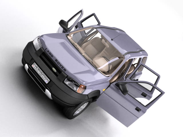

To start this model you will need some schematics or blueprints of vehicle in question, in our case, the Land Rover Freelander.
|
|
Here is how to get your images into 3ds max and ready to use. Open your favourite image editor and cut your blueprints into four pieces: top, side, front and back. The best way to model something like this is to have 4 views. When you have divided up your blueprints and saved your images, open 3ds max and create 4 planes objects (top, side, front and back) and don't worry about their size right now. We'll scale the planes properly to fit the views using some nice tip. Open the material editor, press square on the right side of the "diffuse" icon, pick "bitmap", the file location menu will show up so you can select your image, choose the proper view and press "info" icon. After that, read the resolution settings and set the same value and material to the plane object (if you are not sure how, look at the image). |
|
|
When you finish applying materials to your four planes, move all the planes so that they fit the views properly. You should obtain results similar to the image. |
|
|
Now we can start modeling. I usually start with the hood as a matter of personal preference. The hood will be only element that I will show you on a step by step basis, to help you understand my technique of modeling. Create a small box and place it to become tha back driver's side corner of the hood. |
|
|
Next right-click and use convert to editable poly to make it a poly object.Then remove three polygons where the inside of the hood would be, but leave the ones needed to create the body and grooves. Now move the vertices so that they start to form the shape of the hood in the corner. Choose the proper edges and press the "shift" key to copy them and move these new polygons to draw the curve of the hood (image shows the begining of the operation and which edges to copy). |
|
|
Remember it's very important to pay attention to the proper placement of hood's elements, create the mesh with that in mind; it will help you keep your mesh clean and straight later on. (Image shows the hood mesh with where the important edges will be in green that we'll get to later on. I've also marked some important places you must be careful as you work.) |
|
|
When you feel like you've gotten all of the edges in place and the shape satisfactory, start with creating more of the surface. (Image shows some newly created polygons - selected edges moved a bit with "shift" key, then with "target weld" tool, connected across the gap to fill you that area. |
|
|
Press snap toggle (marked midpoint operation), then with the cut tool divide the created polygons into equal parts. Modify their shape and fix the "hole".(Image shows the formed shape and snap toggie settings.) |
|
|
The next step is to create the polygons which form our hood. Select copy while pressing the "shift" key start copying edges. Try to keep the appropriate shape as you go (It is smart to create quad polygons as by doing so you will get a very smooth and clean mesh without any deformations). |
|
|
When you have gotten the hood's basic shape, it's time to detail it. Use "cut" tool to divide the polygons and move their vertexes. (Image shows how to do it). A better appearance for the hood can be obtained by selecting the proper edges and using "chamfer". |
|
|
Image shows a selected eges and the way to delete and undesirable vertex - with the target weld tool you can also lift selected vertexes to get better look for your hood. |
|
|
Don't worry about the triangle polygons you've created - in this instance they have no influence on the smoothness you mesh. Now you can see the results of the work. Go to the subdivisions surface tab of your object and select it and set the values as shown in image. |
|
|
The standard Meshsmooth modifier does not differ very much from "subdivision surface", however it allows for more elastic work with an editable object. Usually the Iterations value in the display tab should be set to 0. This will speed up the modeling process because you can with low polygon model in your viewport and your object rendered with a high smoothness value. Before you start the next step, mirror the hood so it will be whole. With the mirror tool copy the object and move it so it fits into the views. |
|
|
Then using the attach tool in your 'edit geometry' tab, connect both halves together, vertexes in the center can be connected with the weld tool. When your object is ready, it`s very important to set its center correctly. It will save you time later when you use precise and fast methods of mirroring. In the hierarchy tab press affect pivot only and then center to object. This operation will do the job nicely. |
|
|
To start the next stage of your car`s body, select the polygons of your hood. This saves time by starting with an established part and we won`t need to start the same shape from scratch over again. Now press 'shift' key and move polygons down a bit. Choose clone to object (which polygons and direction of movement shows Image). |
|
|
Select all polygons in the new object and use the flip function. This will cause the polygons to face in towards the hood side, which will give us grooves (Image illustrates desired effect). |
|
|
It`s time to model the front edge of the fender. To do so, select the edges needed and copy and move them to get smooth transitions (Image shows the edge between the new element and the hood and also which edges to select and in which directions to copy them). |
|
|
From now on I will not lead you by the hand for each step. I will only describe the stages of modeling, and my focus will be on problems and tips that will speed up and ease the workflow. Image shows my edges mesh. Looka at how I created the corners, my mesh is clean and simple in these places. You`ll also need to use chamfer in sharp edges/seamed areas to get that nice sharp edge. |
|
|
Image shows a mesh of the whole element. As you can see the main lines run vertically and horizontally and this makes the mesh look much cleaner. In selected places you may need to use the create polygon tool, because we`ve used the 'chamfer' function on the previous edge. |
|
|
Image illustrates how to cut holes in the body for direction indicators. First cut the selected polygon with the quick slice tool and then with the target weld tool move the vertexes to form the proper shape. |
|
|
Use the extrude tool with negative values on your newly created polygon (first time with small value then with bigger) to get an effect like in Image. Copy the extruded element to a new object and extrude it again with the same values (but positive) then bevel it like in Image. |
|
|
Another section of the mesh can be seen in Image. Try to make it very precisely, as it will help you to fil the door and the door glass. Image also shows progres in modeling this element. (Copy and move vertexes as you did with the hood). As you can see this element is not finished yet. I work that way because I did not want to have problems fitting the door later. |
|
|
Image concerns the doors As usual, start with copying polygons from a previous element. Then use the flip option and copy edges to form the shape. |
|
|
Image shows the whole mesh of your door. During modeling of this element, polygons of the previously bulit roof were used which saved me some time. |
|
|
When I rendered my model with the smooth modifier, I saw that the edges that stick to door glass are rounded too much. All changes to solve that problem are shown in Image. |
|
|
I can`t give you the recipe to model a door hande, as evry car has its own type. (Image shows own concept). However it is important to model the right 'hole' for it. |
|
|
Image shows further changes in the shape of the mesh. First use 'chamfer' on the edges marked in red so that when you add the new polygons marked in green that it won`t deform your mesh (the news segment caused some deformation but it`s almost invisible). Now use the quick slice tool in the operation places marked with yellow. This operation creates new polygons shown marked in green. Extrude it with negative values. I also show a place where you should add a crosssection, which is an integral part of that car. To do so, cut the polygons again where I marked it with a yellow line, and then use the 'chamfer' option on the newly created edge. When you finish, select the new polygons and extrude them with negative values. |
|
|
It`s even simpler with the rear door, because all you have to do is to copy polygons that are the first door`s 'groove', then copy the propers edge with a slight shift (it will add a very fine and delicate bend of the sheet metal on the edge) and copy them again, but then you will need to form them to match thee back posts and line of the roof. (Image shows door modeling). |
|
|
Once you`ve modeled the door, you can now go back to the unfinished body (notice, that you have less work to do now, because you have the side door modeled, which helps a lot with modeling the body). As in Image, copy the door's polygons and attach it to unfinished element. Then copy the edges (selected in Image) and move them until you get a silmilar result. |
|
|
The car roof is a trivial thing (in most cars I guess). Image shows which polygons should be copied to the new object (car roof). |
|
|
Use what I've show you already to copy edges and create what you see in Image. In this picture I've also marked places which may cause you some trouble. To create the relief on the foor, move vertexes around and then "chamfer" the edges marked with green just a bit. Apply the same option for the edge marked with red and extrude the newly created polygons with negative values. This will give you the groove between the car roof and border. |
|
|
Let's go move on to the lower parts of the car. The element marked with yellow in Image is basically modeled by copying all the polygons that are marked in red. |
|
|
To create the wheel arches, copy the red polygons and by duplicating the edges you can model the proper shape (Image illustrates which polygons to copy and the shape it should have. Edges to "chamfer" are marked with yellow.). |
|
|
Image is a view of the final front wheel arch. Cut polygons and move your vertexes to make it look more oval. Using the same method, make the rear wheel arches. To archive a more interesting look, move the lowest vertexes out a bit from the others. |
|
|
Both objects should now be connected using the target weld option along the edges marked in red on Image all the way along the seam. |
|
|
In Image you can see the final front bumper's mesh. You can probably figure out from here how to build this, so I'll just tell you to watch out for the spot marked in red. The number of segments and vertex placement must be correct to make the headlight look correct. |
|
|
You can see the next changes in Image. "Chamfer" red edges to fit the side door (over handles). Delete yellow polygons to make space for the headlight. Remember to make new polygons which are groves in this case. Copy the edges inside the hole. To keep the square look of the headlights use the "chamfer" option for proper edges. |
|
|
Image shows the hole already cut out for the lights and rear bumper. Copy the yellow polygons into a new object and then extrude it with positive values - they will be the reflective lights. |
|
|
Image shows the rear door mesh. Copy the edge polygons from the body and bumper objects over to a new object and connect them. To hollow out, extrude with negative values proper polygons. |
|
|
Now it's time for glasses and seals. Let's have a look how to create them. It is important that these objects be double-sided. It will allow you to archive realistic lightning effects, like caustics. As always start by copying proper edge polygons from the door. Then move the vertexes to make the glass thinner than the door it is coming out of. This can be seen in Image. |
|
|
Here you can see 2 steps of creating window. |
|
|
Finally you need to fix the smooth corners for the glass. To do so, select all glass edges and "chamfer" them with very small value. (Image shows effect before and after). |
|
|
Seals can also be done from the door. Just try from them so they fit over the door and glass. You do not to worry about red place in the picture; becouse it will be covered by side mirror (Image shows modeled seal). |
|
|
Here you can see geometry of others windows. |
|
|
With exactly the same technique crate the windscreen and rear glass. First create slit around the glass, then copy the polygons and shape it (Image shows both meshes). |
|
|
In image you see the light. Copy the proper polygons from other parts of the body, then copy the edges using the technique that have already have been shown in this tutorial and make any tweaks that you need. Look how clear and simple the headlight mesh can be becouse the number of segments in the bumper and hood elements and their arrangement are proper for this vehicle. |
|
|
The chassis can be done by selecting the proper sheet metal edges and using what you've learned so far. Copy selected edges, move them to the center of the car |
|
|
Select the newly created polygons. Copy them to new obiect (chassis), select the new elements and delete them. Now we have a chassis and the untouched shape of the original. |
|
|
Follow the idea with other parts of chassis until you cover whole bottom of the car. (Image shows bottom view of chassis). |
|
|
Image shows a tire I created. I will not show you how to do it, becouse I made it from a tutorial that you can download from www.suurland.com (In my opinion best way to make a tire). |
|
|
What I will do is show you the rim technique that i used. There are many different type of rims, so this method is not universal, however it can be used in many cases. Let's start with standard tube object. The number of segments will be relative to the count and shape of the arms. This will be the 6 arm rim, which means we want to give it 18 segments. Now select the proper polygons and use bevel option, than move poper vertexes around to obtain a basic shape of the rim. |
|
|
When you have the basic shape, extrude the same polygons one more time and create a new surface with the create option, marked with red. |
|
|
Select right edges (border function is quite useful here) and scale the while pressing the "shift" key from the center of the object. |
|
|
Final step, select the right edges and "chamfer" them, it will form nice rim. |
|
|
A final touch is to connect appropirate parts together, just like I showed you with the hood at the beginning of the tutorial. Copy the others with the mirror function, (remember to active reference option, it will allow you to transfer proprieties of the original and will give you the ability to manipulate the original element). Images besides and below shows the final mesh of the car. As you can see there are some additional details that I have added that you should be ready to build to complete your freelander. Keep trying, despite the difficulty, if you really wont to become successful. |
|
|
Here you can see geometry of the back. |
|
|
Here you can see the final model from front view. |
|
|
Here you can see the final model from back view. |


LEAVE A COMMENT


|

|

|

|

|
 Customer zone
 Your orders
 Edit account
 Add project
 Liked projects
 View your artist profile


COMMENTS