We have added new 3D Scanned Assets

Shop Now
Search
Cart
Sign in
  • offerCustomer zone
  • offerYour special offers
  • offerYour orders
  • offerEdit account

  • offerAdd project
  • offerLiked projects
  • offerView your artist profile

  • Dark mode

Information Clause

In accordance with the art. 13 section 1 and 2 of the European Parliament and Council Regulation 2016/679 of the 27th April, 2016 on the protection of natural persons, with regard to the processing of personal data and on the free movement of such data, and repealing Directive 95/46/EC (General Data Protection Regulation), hereafter RODO, I hereby inform that:

1. EVERMOTION S.C., 8 Przędzalniana Str., 15-688 Białystok, Poland is the Administrator of your Personal Data (APD)

2. Data Protection Inspector can be reached through e-mail: iod@evermotion.org

3. Your personal data are to be processed on the basis of art. 6 section 1 letter a, b and f of RODO in order to:
a) prepare, conclude and execute the agreement and for other purposes approved by you,
b) to execute the legitimate interest like marketing of products and the agreement, claim assertion or defence against claims resulting from the law regulations.

4. Entities entitled to the reception of your personal data may be the authorised public bodies; mail providers; providers of the services covered by the agreement; responsible for debt recovery, keeping the archives, document utilization, legal consulting, technical services, IT services and accountancy.

5. Your personal data shall not be transferred to the third country, nor to the international bodies.

6. Your personal data shall be processed within the period of the agreement and upon your additional consent until you withdraw it. APD shall keep the data for the period of any civil law claim execution connected with the agreement.

7. You have the right to demand an access to your personal data, to correct or to delete the data if there is no other basis for the processing or any other purpose of such processing or to limit the processing of the data, to transfer the data to another administrator and to raise objections to the further data processing if there is no legal basis for further processing and to withdraw any previous consent.

8. You provide the personal data voluntarily, however they are necessary to conclude the agreement. The refusal of providing such data may result in the refusal of the agreement conclusion.

9. You have the right to lodge a complaint to the Personal Data Protection Office when in your opinion the data processing violates the regulations of General Data Protection Regulation of the 27 April, 2016 (RODO).

10. Your data will be automatically processed, including the form of profiling.
11. You are obligated to forward above mentioned information to your representative, especially if you appointed this person in the agreement as the contact person or as the representative for the agreement execution.

OK

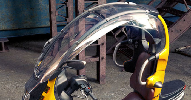
BMW C1

Makar Verigo 2008-10-06 00:00 tutorial  > 3ds MAX  > misc

INTRODUCTION

"The BMW C1 is an enclosed scooter or feet forwards motorcycle, which was manufactured by Bertone for BMW. It was intended to combine the advantages of two-wheeled motorized transportation with the strengths of the automobile. The idea was to offer the convenience of a scooter or motorbike but without many of the associated dangers or hassles. BMW tried to add passive safety and car-like crash testing to the scooter. It claimed that in a head-on collision, the C1 offered a standard of accident protection comparable to a European compact car. Since going out of production, C1s have found new homes with collectors and as pit-bikes for some of the Formula One Grand Prix teams".

In my noncommercial projects i try to select the subject and components in the way of using the maximum of my skills, and putting the tasks to solve them using new methods. In particular, i was interested in industrial and automobile design, as i have no experience in these fields, and my work in this way could grant me new opportunities in skills' development. Considering this, C1 proved to be interesting. I bumped into it accidentally, looking through Google Images. The style of this concept seemed fresh and unconventional, it stended out of about 20 other images on the page, so the next moment i was looking for its blueprints. 
 
 
MODELING
 
In the beginning I had no idea how this project will look like in the end. One thing was clear for that moment - the final image must satisfy the requirements of A4-A3 printing layouts and render options are to be for high res. The motor scooter itself meant to be the main and most worked out part of the overall composition, and further planning based on the most advantageous views of it. Thus at the first stage the main goal was to make an authentic model. And that was the moment that problems arised. The one set of blueprints I could find was poor detalized and incorrect - placings of some objects didn't correspond each other on different views, so I could use them for forming the approximate cargo body proportions only.


This defined modelling sequence - assembling the car body at first with constant fitting its parts to each other, forming the silhouette and main proportions, then placing the details at basic forms.


My technique itself is nothing special - simple polymodelling, carried out in the majority of existing 3D modelling software. As usual, I begin to build the form from the one polygon: a plane with one segment, convert it to Editable Poly, switch to the edges editing level and move them with pressed SHIFT key, "pulling out" remaining polygons. If I need to join model parts, I switch to vertex editing level and connect them using Weld, Target weld or Collapse command. If I need to cut out the model part or to add more edges in places where the grid is not dense enough, I use Cut and Slice commands at polygon editing level or Connect command at edges editing level. If topology of model satisfies me, but it's form and proportions do not, I use Free Form Deformers. Also I have a habit to use Edit Poly as layers, like in the Photoshop or Zbrush, to have oppurtunity to compare the things as they are and were, or to undo it at any moment.


MODELING - CONTINUE
 
In this work Edit Poly's standard features were surely enough, but it's useful to remember: they can be extended with the scripts like Advanced Poly ( https://www.ap.nine.ru ) or PolyBoost ( https://www.polyboost.com )

After the assembly have been done, I took 4 views seemed interesting and descriptive to me.


On the base of them the whole scenery was done, as planned (the last 4 views, which made it to the final set of images, were selected with taking into account the surroundings after modelling stage was finished).
At this phase I intended to use studio renders only, but wasn't sure if this variant suits me. Had to complete some test renders to get the rough idea of the result. To achieve this, I have set the test lighting with mininmal settings, then selected HDRI to be well color-balanced, for the white material in the picture stayed white without additional camera adjustments. It was easier to check changes in materials this way, and to stay sure they will look naturally in different lighitng schemes.


Then, I created some simple materials and rendered a couple of rough images of the studio


Wanted to make two variants of lighting, to show how the model looks during day&night, and in this regard i was disappointed with the result: in the studio with dark background the difference in lighting wasn't really noticeable, and the studio with bright background looked plain and somehow unfinished. Thus I came to the decision to try the variant with surroundings - it helped me to create complete and complex picture with elements from different areas of 3d design, I could check my skills at all phases of the process and get maximum from this project. Didn't make sense to restrict myself by creating background only for one view and leave the others at the studio, while the whole 3d scene meets the requirements of model's presentation for each selected views, and could be used in animation as showreel, if i ever attend to it.
The subject for background was defined at once, I always wanted to create something linked with industrial culture, and here I was given the opportunity. At that moment I already decided to "dirty" the model some. Industrial background in this case takes the role of aggressive environment, explaining the stains on the hull by its existence, makes some contrast wit C1's futurisric look, and also lets me to play up the black&yellow color schematics of some dangerous mechanisms. All this provides interaction with the model itself and its surroundings, makes it organic and associated.

The next phase was the search of references for the environment.


The work on references was completed in:

1. I made a list of items I'd like to see in the picture, and made some sketches of the scene with dummies made of primitives.
At this stage i needed to set the volumes. I didn't wanted to make surroundings structure too complicate and fractional, in order to keep viewer's attention on the bike, so I tried to build the space mainly with large forms.

2. looking for colors, materials and textures for the objects selected at the stage 1.


TEXTURING - MATERIALS

Okay, modelling is finished, all objects scaled and placed, views are selected, lighting's ready. It's time for textures and materials.

All models in the scene can be divided into three groups by the complexity of their unwrapping.

1. Models, for which one of the standard variants of UVW mapping's enough. They have simple form or they are some undistinguished details of more complex object. Mostly screws, screw-nuts and like this, as well as objects in the depths of scenery and poorly alight ones.

2. Models which need unwrapping on the base of standard mapping which demands correction "by hand", but without strict accuracy. For instance, when you need texture scales of different objects to roughly correspond to each other, or when you need to place some stains somewhere without taking into consideration to the seams and terxture stretching, 'cause the model's form lets you to hide it easily. Most ojects of the scene are in this group


3. Models, which unwrapping need to be planned or made under specific requirements. These are hull's parts:

3.1 Shroud. Lines of the texture need to be parallel with seams on the hull, thus the proportions and contour on the unwrapping are to be the same on the hull and its parts. These requirements, for instance, exclude usage of Pelt mapping


3.2 The tray. There must be some relief on the plate on the bottom of the hull. The easiest way to make this relief is using of Displace. As relief's pattern should be balanced along the hull, I needed to use planar mapping to the displaced part, to preserve its contour and proportions, and to bould up the rest of the mapping around it, avoiding texture distortion and hiding the seam, which was achieved by using Pelt Mapping, Relax and handmade vertex positioning.


Materials could be divided in two groups:

1. Standard ones - used in most cases, are enough to achieve simple tasks. Basic principle is to achieve the goal by playing with basic material settings, usage textures for slots Diffuse, Reflection, Glossy and so on, and corrections of these textures with means of Output block in their settings ( or by means of plugins like Color Correct https://www.cuneytozdas.com/software/3dsmax/).


2. Composite ones - used in specific tasks, built up on combinations of different materials or textures by means of masks or Procedure maps. Have branchy hierarchy. Striking example in this work - ground material.


TEXTURING - GROUND

Formerly all the textures were prepared in Photoshop, in material editing used finished images that was received as the Photoshop output. If I needed to edit the texture, I've returned to Photoshop. Exceptions were in cases when only contrast should be changed - I used curves in texture's Output menu for it. It's standard approach, which lets someone to edit materials without complicating its structure, and in the beginning I wasn't intended to digress from using it.To begin, I needed to define resoluton of the texture that I had to work with.
There was no sense to make a unique drawing of the texture for the whole object, as it would be partially hidden by another models. Besides that, for that moment I worked in 32-bit WinXP and was restricted by 2GB RAM limits for a program, I had to lay all this scene in such a Procrustean bed. I wrote "3gb" line in boot.ini and it gave me a little space to act, but I still needed to use memory sparingly. So, when unwrapping was done, I scaled it in such a way that 3dmax's unwrap projection contained only these parts, that could be seen in two views minimum. This way I've got a square with the model of bike in the centre of it - this square doesn't cover all visible ground areas which leads to texture tiling, but, as it doesnt fully appear in field of view of any camera in scene, tiling won't be visible, as tiled part of the texture'd be outside of the screen, or hidden beneath environment


Texturing region was determined, now here comes the resolution. To define it, I used 1000x1000px texture for the object, by which I intended to imitate ground, and made some renders in final resolution, increasing tiling until aliasing disappeared. Figures I got looked bad - the tiling measure increased to 12. It means that I needed to use 12000x12000 texture to get decent picture of ground, while for that moment 3dMax crashed when I tried to use textures with 4096px on larger side.

One thing I could do is assemble needed texture from smaller ones _inside_ 3DMax this way:
- I took some texture of tarmac, rocks, earth, mud and sand
- set the texture scales to the scene scale by setting tiling measure for each one of these textures
- made lighter and darker variants for each texture
This way i got about 30 layers I needed to blend with each other to "break" the tiling of each layer and to remove synthetic uniformity it made, making the final texture more natural and credible. Following the same principle I also made sure if tiling of textures with same resolution have different values, in order that seams between the tiles on different layers don't lay in the same places. Then, using the Mix map, I began to blend these layers.
In the beginning i intended to use procedure maps as masks, but wasn't satisfied with the result, and decided to use textures. I was limited in their maximum resolution as before, but, as they were used to mark the sections of layers' mixing, they could be stretched without risk of worsen the final image, as the scale of layers was remained the same. Cheating it is, and it led to some artifacts, but they were easy to remove with Healing Brush in Photoshop


At this phase the scene was highly unstable, 3Dmax was ready to crash in response to any careless action, that's why the ground material is primitive - I've placed the final texture in Diffuse slot and finished with it. For displace I used a copy, to have opportunity to control displace's height and direction, without changes in Diffuse.


LIGHTING

I wanted the lighting in the scene to be mild, with degraded shadows, which is typical for summer cloudy day. And the light needed to be directed to delineate the model's form and to add some depth to it by contrast of lighted and shadowed parts. For these goals HDRI with Dome Light were enough for me - test HDRI meeted all requirements mentioned, so I kept going with it.
I adjusted Dome as direct light (i.e. I don't turn "store with irr.map" on). In this mode Dome with HDRI gives more correct and detailed lighting, than just HDRI, set as texture for Environment


Also I tried "store with irr.map" turned on" variant - all highlights in the scene were practically washed out, and to keep shadow details, i had to twist out Irradiance Map adjustments, which made render time longer with worser results.
As this scene is of exterior type and it has few amount of unseen and unreacheable by primary lightng places, secondary lighting's influence is so insignificant, so it was needless to adjust its settings while getting realistic and pleasant look in lesser time.
Nevertheless, I turned "store with irr.map" on in Dome's settings for night renders, but only because as direct light there were plains that I used to imitate flashlights


Some more plains were placed inside the headlights.
I turned off caustic in global lighting settings to decrease render time. Thus glass material with Glossy effect let the light through badly, and headlights almost gave no reflection to nearby surfaces. For night renders I decided to accentuate this effect and for this purpose placed more invisible plains at the outer side of headlights.


RENDERING

Render settings based on LWF. Detailed description you can read here:
https://www.gijsdezwart.nl/tutorials.php
and here: https://www.chaosgroup.com/forums/vbulletin/showthread.php?t=33917


POSTPRODUCTION

Working with LWF is often results in final picture with low contrast and weakly saturated colors, that's why the main goal of postproduction is to strengthen them. I have no general algorithm of actions, for each image i have specific sequence. Below is just one of the variants, but if I work with LWF, I begin with the same: I save the result of render in 32-bit format (.hdr or .exr), to wok with it like with HDRI ( to apply Tonemapping in Photomatix or in the photoshop, for instance). All the whys are in LWF's description in the link above, and it's quite obvious: 32bit formats, unlike 16 or 8 bit ones, contain enough information about image for reproduction of linear color space, thus providing detailed correction of image's color and brightness. So there is some sense make all the corrections before image convertation, to stay in 32bit mode as long as possible, and to go into 8 bit in the end of work, or when there is necessity to use software which doesn't work with 32bit formats (most plugins for Photoshop or AfterFx).
In my case it looks like adjustment of gamma, brightness and contrast with Exposure tool with subsequent color corrections by curves. If there is necessity, for instance, to work with layers or use Lens flare in AfterFx, then I have to convert image into 8bit


Postproduction of night renders is different from day ones mostly with my active usage of Lense flare to make headlight reflections and hull's glares more realistic


That's all :) Hope you found this helpful.
Cheers.


AUTHORS INFO
Makar Verigo
mverigo at yandex.ru


Author: Makar Verigo
Tags:
You may also like...
3D models for game developers: from houses and skyscrapers to dilapidated buildings

3D models for game developers: from houses and skyscrapers to dilapidated buildings

Game developers understand the importance of visually stunning and highly detailed environments in creating immersive gaming experiences.
×

LEAVE A COMMENT

You need to be logged in to leave a comment. Don't have account? Register now.

CDC1986 03:05:11  |  27-01-2011
Very nice!
Oliya 13:59:40  |  27-04-2011
thanks~It's useful~~ *^^*
Oliya 14:18:41  |  27-04-2011
Can you send me the scenes file? I want to practice~ Thanks you so much~~~ xuanwuji_yzp@sina.com *^^*
Oliya 14:18:42  |  27-04-2011
Can you send me the scenes file? I want to practice~ Thanks you so much~~~ xuanwuji_yzp@sina.com *^^*
guangning1 12:38:14  |  17-11-2011
you are good ,Thanks you so much,Can you send me the scenes file? 764349034@qq.com
kedr_100 23:23:36  |  23-06-2012
hi Can you send me the scenes file? I want to practice~ Thanks you so much~~~ ohmur2012@mail.ru *^^*