Evermotion: More Than an Asset Library
How Evermotion became a full-scale production partner for archviz, automotive and synthetic data.


Total: € 0

- Creating Guide Scene
setting up the guide scene.
 |
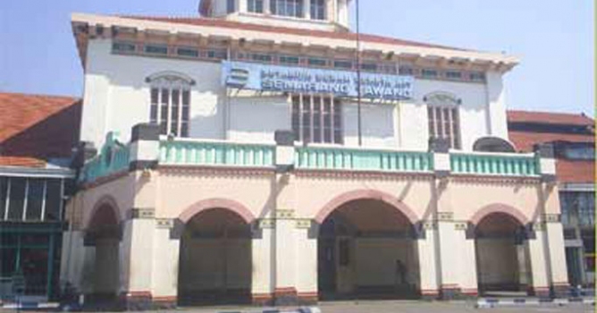
We have two pictures as reference. These picture show a train station. It's located in Semarang, which were built during dutch colonial. Exactly I don't know any information about its measurement definitely. |
 |
Open MAX, Displaying the Background in the Viewport. Viewport "front". Click "Files.." button. Check Lock zoom/pan. Match Bitmap |
 |
Background Texture Size we need fine detail in viewport background. |
 |
Maximize your viewport and u can turn off grid. |
Point Perspective n Horizon.
 |
Use Line to find Vanishing Point. |
 |
Vanishing Point We have had a vanishing point/point perspective. Its location must be arround there. For the next step, we should look for other vanishing point/point perspective. But for this ref image, it will be so difficult to find them. |
 |
To solve problem of seeking other point perspective, draw line from that building basic form. |
 |
Additional Line Guide Horizon |
|
Set up a rendering background RENDER (same as ref image resolution, ex 1024x768) |
Additional guide scene
 |
Reset MAX Repeat prev steps. there is such different, point perspective or vanishing point is out of the scene. Look for the horizon position by using box. Lengthen box untill passin VP. horizon cut the VP, that is good forerunner. |
 |
Additional scene is ready now. Set up a rendering background RENDER. Save as Blueprint2.jpg |
- Camera Matching
to match the perspective of a camera to a photograph. We will need accurate scene measurements.
but if we don't have any information about measurment we can still make an estimate and matching the perspective to ref image.
Measurements
 |
Reset MAX at frontview, use ref image as background. Analyze ref image. find any object can be use as measure comparator. i use that oldman in the ref image. we estimate height of that oldman is 155cm(too short..no problem) Create Box with height as high as building(line guide). Rotate box corresponding to Z axis perspective. |
 |
Ctrl+N in any numeric field. to display Numerical exp ev. as a calculator. 155cm x 7 = 158.7V we get h = 10.85m, V = 0.0678 |
 |
Create a box according to width building. 304.8 x V = width. we get w = 20.665m |
Camera Matching1
 |
Reset MAX Displaying the Background in the Viewport. Creating Basic Object |
 |
Length we estimate length depend additional line helper/guide we have made. we assume that length is 30m. |
 |
Setup Camera Matching right click on 3d snap, check only vertex. then click snap to activate (S). |
 |
Create>helper>Camera Match>Campoint. |
 |
Camera Point helper/3D Point. Create point wth clockwise, so we can easily remember. Open box object properties, uncheck backface cull. and check see-trough. |
 |
Assign Position/2d point. utility>Camera match>assign position. see pic. warning,"background image ratio should be set to that of the renderer, fix?" yes, ok. a red plus sign displayed on the bitmap. |
 |
Create camera. we can see, box not match with which we expect. that mean estimation of our length is wrong or position of vanishing point is not accurate. |
 |
Fixing change position of 2d point and assign new position. we just need to assigning new position of campoint05 and campoint06. Change the position with path at line guide we have made. |
 |
With camera selected, click modify camera. at camera modifier, Check show horizon. almost perfect, fix it. |
 |
Until we have satisfied with match result. then we see camera position which have been made. |
Camera matching 2
Camera matching for second image.
 |
we should hide 6 campoint we have made into different layer. |
 |
on other viewport (say a left viewport), change to perspective view. add viewport background with "blueprint2.jpg ". Create new layer. rename with helper2. Create campoint. Assign position. warning again, ok.. before we create camera, uncheck "use this point" at campoint 1-6, because we dont need now. Create camera, |
 |
Open blueprint2.max, create additional line guide. and render>save as blueprint3.jpg. |
 |
Switch to matching work, change viewport background with blueprint3.jpg. re-set selection filter>all Create campoint11 and campoint12. dont forget to activate snap. Assign campoint11-12 position. Create camera, fix it. |
 |
create new basic object and match with blueprints. I hope this tutorial was useful for you. trust yourself..and sorry for the english. |
|
workflow:
|
|
|
Links and references: other Architectural reference image to 3d, tutorial:
Point Perspective: Other:
|
|
problem and any question
fell free to contact me
email: [email protected] (with o).
YM: Fabolousview


LEAVE A COMMENT


|

|

|

|

|
 Customer zone
 Your orders
 Edit account
 Add project
 Liked projects
 View your artist profile

COMMENTS